With over 18 years of experience working in the Information Technology and Computer Science field, I have wondered how information can affect us as human beings and our brains. During the years, I invested a reasonable amount of time reading different brain models and how they interact with information. Unfortunately, no model measures the level of stress and distress information could put on our bodies. This article aims first to give a simple explanation of what the Internet is and how it could be connected to human brains and second to provide a sample formula of how information coming from different sources could affect our health.
This work uses some terminology coming from the works written by the following authors – Norbert Wiener, Freeman Dyson, David Bohm, F. David Peat, Peter Senge, John Polkinghorne, Edmund Bourne, Marcello Vitali Rosati, and Fredmund Malik. The ideas from these works helped me prepare this article and clear out my understanding of how the brain and information are supposed to work. I would suggest every specialist in Artificial Intelligence and Machine Learning read their works to better understand our reality and how it is supposed to function.
But let’s start with a couple of physics-based definitions:
Continuum: The traditional mathematical model of quantum space usually involves matter and energy. As some of the listed authors state, the next step is to add the information into the model and finally get a unified model consisting of matter, energy, and information.
Information: However, an excellent question arises – what is a piece of information? During the years, I read multiple definitions of the information, and it seems the scientific community can not decide which one must be the canonical one.
Entropy: For this article, I shall use two of the definitions of information based on entropy – first, the definition provided by the standard quantum space-based model, where the entropy shows the amount of energy in a given system and second the one supplied by Claude Shannon, which could measure the amount of information transmitted in communication. Most researchers consider information entropy and quantum space-based entropy directly linked to the same concept, while others argue that they are distinct. Both expressions are mathematically similar. Additionally, we could theorize that the information size can represent the amount of quantum energy going through our brains.
Dynamical system: In physics, a dynamical system is a particle or ensemble of particles whose state varies over time and thus obeys differential equations involving time derivatives. An analytical solution of such equations or their integration over time through computer simulation is used to predict the system’s future behavior.
In other words, we could use a dynamical system to describe the continuum, including all human brains and the Internet. At the same time, we could define the human brain and any computer-based device as a dynamical system (actually, a neural network is a type of dynamical system). And we could use entropy to “send and receive” information/quantum energy from the continuum to the human brain or a computer-based device.
Two additional definitions will help us to finish drawing the picture:
Passive information: By definition, we could define passive information as the entropy of a system, which is in a stable state and there is no additional energy, but if we put more energy into it, we expect the resulting entropy to be that one. Such systems without additional energy are newspapers, books, articles, computer hard drives, flash drives, etc.
Active information: On another side, if there is energy transfer into a given system, we could expect this transfer to come with the so-called quantum potential, and this potential contains information, which we could define as active information. Examples of such systems could be our brains reading books, watching videos, or listening to music. We could expect our brains to store information/energy the same way. Additionally, we could categorize most computer-based devices the same way.
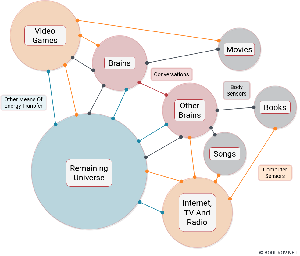
After we have described all the needed definitions, let’s draw the whole picture using them as building blocks. We have the continuum and number of dynamical systems attached to it. Every system can receive and put energy/information into the continuum. Some systems are stable and only put energy/information in the continuum when other systems put some amount in them. Other systems are constantly in motion and emit and receive energy/information without breaks.
Many researchers categorize our brains and computers, such as reality engines – aka interpreters of quantum energy coming through them. However, these reality engines must be treated as emitters because human brains and computers emit energy via video, audio, motions, temperature, etc. Systems without additional energy are newspapers, books, articles, computer hard drives, flash drives, etc. could be called reality reflectors because they need a boost of energy to emit anything. In short, that way, we could connect the continuum to the virtual world “virtualized” by the Internet. But, let’s try to define some reality engines types:
Brain: Brains use natural information/energy and work by natural scientific laws. The reality presented by them abides by the physics rules, and anyone could not modify these rules.
Internet/Websites: The Internet mainly uses natural information/energy; however, the reality presented by the Internet could or could not abide by the natural laws. Many programming languages could define functions, which do not map to the rules defined by physics. Additionally, we could not know the quality of the information/energy stored on the Internet as passive information.
Video games: There is almost no limit to what kind of information/energy you can put into video games. The systems defined by the data in the video games usually could not occur in Nature. Additionally, video game engines often do not abide by the laws of physics. The primary purpose of almost all video games is to give the user the sense of easy and fast power, so instead of spending years of hard work to achieve something in the continuum, the user can do it in a couple of hours and feel fulfilled.
On the diagram you can see a sample dynamical system representing the energy transfer happening in the continuum. Most transfers happen thanks to a sensor activity. Whether there are other means of energy transfers rather than these using sensors, we do not know yet.
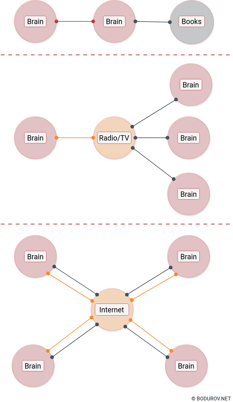
There is an interesting aspect of how the information/energy travels through the continuum. To reach from one reality engine to another, it naturally has stable paths. We could furthermore call these paths reality bridges and define them the following way:
Natural: By making a physical object (a passive or active information system), which travels the continuum using any transportation such as cars, trucks, planes, etc. The bandwidth depends on the capacity of the dynamical system.
Broad-casted: The information/energy travels using paths that are not bi-directional. So the energy is only transferred in one direction. However, multiple reality engines can receive this information/energy at the same time.
Peer to Peer: With the emergency of the Internet, now we have an even more connected topology, where one reality engine can receive and emit information/energy from/to another reality engine. Me writing this article is doing precisely that – emitting information/energy. My brain using the keyboard sends information/energy to my computer, which sends the information/energy furthermore to many computers.
After finishing the architecture presentation of our collection of dynamical systems connected to the continuum, let’s formulate two definitions used in the Information Technology field, which we could transfer to our collection of systems:
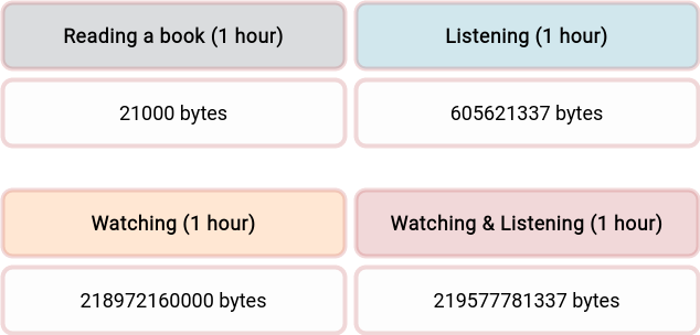
Bandwidth: The amount of information/energy that could be transferred for a time unit using a reality bridge. On the table, you can see the bandwidth which different reality bridges offer.
Latency: The delay of receiving the information/energy after the initial emit. We could expect that the longer information/energy travels, the more energy would be lost. However, the reality bridge would preserve the information.
After having all of these definitions and rules, let’s analyze in this current setup how information/energy could affect human health. We already perceived that the human brain may be working as a reality engine, and it looks like it is a dynamical system. At the same time, we can put and remove information/energy from this dynamical system. And every dynamical system has its capacity of states. Two questions arise – what happens if we keep pouring information/energy into the system but do not remove any from it, and could we expect to have some filter where the information/energy intensity could be decreased.
On the first question, in case of computer configuration, the computer will malfunction. In the case of the human brain, the short answer is – we don’t know. Based on the different theories I read, I could assume that pouring too much information into our brains could lead to psychological problems and psychiatric diseases. Another interesting fact related to our brains is that most psychological problems and psychiatric disorders could not be related to physical brain damage. The condition is entirely on a reality perception level, or we could assume it could be a problem with dynamical system capacity overload.
On the second question, in the case of a computer system, filters are already in place; however, these filters work too low level. On the so-called application level, things become more complex, and the computer needs human help. Regarding the brain, the situation is much more complicated. Based on our life experience, we could expect the intensity of the received energy to be based on how emotionally close to us is the reality engine emitting it. If it is our child and we receive negative news about it, we could expect the information to be with the highest intensity; however, if we receive negative information/energy for an unknown kid on the Internet or the TV, we could expect this to hit us with less power. Based on this observation, we could assume that there is an information/energy filter in our brains. It seems that this filter is based on the social distance (which is partially based on latency) to the reality engine emitting the information/energy.
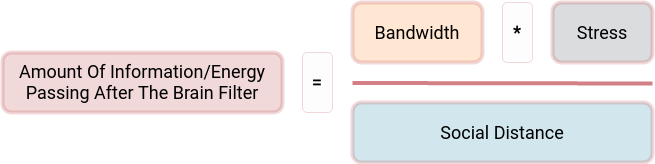
And finally, let’s combine all the upper statements into a single formula:
Bandwidth is the raw bandwidth of a 1-hour video and audio data chunk, calculated in bytes.
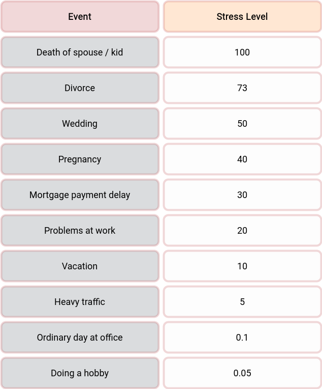
Stress is the level of stress which we could attach to the information/energy transfer. Check the different levels in the table, coming from the beautiful Edmund Bourne’s work on psychological problems and psychiatric disorders. I modified the table slightly to support more common daily events.
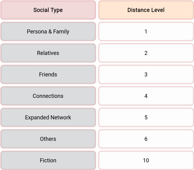
Social Distance is the social distance modifier, which we could find in its table. The modifier tells us that if we are experiencing the information/energy transfer from the first-person view, it will hit us the strongest, and if we hear that someone we don’t even know has a problem, then it will hit us ten times less.
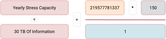
According to Bourne’s book, the typical yearly amount of stress for a human being is around 150. Some people could endure higher levels, others less, but the median is around 150. We could calculate the number of information/energy an average human being can survive for the year using that data. After passing this limit, we could expect the person to start feeling the effects of distress. Another interesting assumption is that we could expect the level of stress to be reduced automatically over time. It seems our brains are designed to lose energy/information over a given time period and thus reduce the stress level to some predefined level.
If we play with the formula, we could see the following observations:
One could endure 1 hour and 30 minutes of information regarding the death of his/her kid per year
One could endure around 15 hours of the information regarding the death of someone unknown’s kid per year
One could take about 1500 hours of active office work per year
One could do his/her hobby about 3000 hours per year
Surprisingly the formula looks correct for most real-life social events. There are some edge cases with what happens if you read about your kid’s death in the newspaper. Will this information/energy hit you with less intensity than the video/audio equivalent? For sure, no. Probably, we could add a modifier based on the stress level per reality bridge type. However, the needed work to make the formula work for every edge case is far outside this article’s scope.
In conclusion, I would say that I do not pretend this work to be entirely scientifically correct. There are many scientific holes, which we could not prove adequately. Additionally, this article is my understanding of the listed authors’ works. I am not a physicist, nor a psychologist, and some of the nuances of the mathematical models used in these works could be too complicated for me to understand entirely.
However, for sure, the following questions need answers:
How does the Internet affect our brain?
How much information/energy can one put in his/her brain before burning out?
Could we relate the burnout symptoms to too much information poured into our brains?
Is the World moving faster or just the information/energy in it?
Must the amount of information/energy stored on the Internet be frightening to us?
Could getting this information/energy on a daily basis affect us in the long term?
Could the mindful and wellness techniques listed everywhere help us remove part of the information/energy from our brains?
Is the information/energy from our brains removed, or is there another mode of working where the active information is stored on standby?
And many more
I am convinced that some day, we shall receive answers to these questions, but with our current knowledge, the answer is – we don’t know.
In the last two parts of this series, we discussed our network protocol and the architecture of our body camera system. We shall discuss our backend recording and streamers service in this final part. After that, we shall present the budget we burnt for this MVP, and finally, we shall discuss why it did not work.
There are multiple server video streaming solutions across the market. Unfortunately, most of them require installing new desktop software or plugins. At the same time, we saw that no video storage format is codec agnostic and could support multiple frames using different codecs. All these weaknesses forced us to develop our storage format for our videos. After a reasonable amount of time of thinking about what would be the format we need for this kind of work, we formulated the following requirements:
Blazing fast append: We wanted to write down the incoming frames as fast as possible. Every slowdown of reindexing the frames would decrease performance and increase the cost.
File-based: Storing a significant amount of data into a database is the wrong approach for media-based files. So the file format had to be binary based. Because of the previous requirement, we had to skip the index. Every index recalculation would end up in a lousy performance.
To support telemetry: We did not stream only video and audio data, but we also streamed telemetry. There had to be a way to stream its frames as well. Plus, there were use cases in which the user of the body camera could want to stream only telemetry, but not video.
Websocket streaming: Since we can not support another streaming format, we decided that streaming from our server to the web browser clients in the headquarters will be based on WebSockets. To do this properly, we had to implement our video player.
Fortunately, if we analyze our network protocol, we can see the following characteristics which will fulfill the requirements:
Partitioning: Every network packet has a unique user id and date. And that is enough to determine the filename of the stream uniquely.
Counter: Every network packet has a unique counter value, and this value is attached to the date. At the beginning of every day, we moved the counter to zero. If we analyze further the logic of this counter, it could be used as an index key, by which we can sort by time the whole stream.
Supports telemetry: Our network protocol supports telemetry by default.
Supports WebSockets: We can reuse the same binary message we received from the Android device for WebSocket streaming. The message must be just encoded properly for WebSocket streaming.
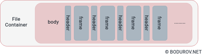
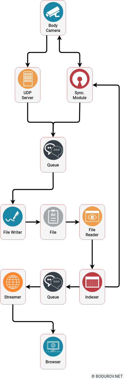
You can see the modified version of our frames container on the diagram. It follows the header:body format, where the header represents a metadata structure for the next frame. By iterating the whole file, we could index the metadata into our server’s memory
With the information from the previous bullets, we can define the following logic. We append every incoming packet to its corresponding file on the filesystem, similarly to what pcap is doing with the network packets. At the same time, another process is reading the file and building the index in memory of our service. And the service uses this index to restream the recorded network packets through web sockets to the web browser player.
To implement the described logic, we decided to build the following system modules:
UDP server listener module: The idea of this module is to listen for UDP packets and reroute them to a concurrent queue. The FileWriter module later consumes this concurrent queue.
Concurrent queue module: Having in mind that we can have multiple process workers, instead of using mutexes or any other synchronization mechanisms, we decided to communicate using queues between the processes.
FileReader module: This module’s primary duty is to read the file packet by packet, using the already loaded index.
FileWriter module: The idea of this module is to take the packets from the queue and store them into the file. Partitioning per file per queue was implemented, and every file had a FileWriter process.
Indexer module: It reads the file and indexes the network packets into the memory. After that, it is used by the Streamer module to stream data.
Streamer module: This was a collection of processes that started by given offset and used the indexer module to send data to the WebSocket server.
Web browser player module: The module was used to decode the network packets coming from the WebSocket server and play video and telemetry data in the browser.
Synchronization module: The idea of this module was to provide a way for the synchronization of missing packets between the Android device and the streaming server. We used the index module to return a given user and date for which frames are missing.
One can easily modify the proposed architecture to support cloud deployment and high scalability by replacing the concurrent queues with message brokers and the local filesystem with GlusterFS.
You can see a sample system architecture on the diagram describing the listed components. Arrows represent the data flows and how the data passed through the system
After we finished the technical details of the implementation, let’s discuss how much it cost for us to implement the MVP:
Budget:
Android device (200$): We decided to use a standard Redmi 3 device. It supported all the needed features, and it had an excellent battery.
Extended battery development (3000$): We developed two battery versions because the first one was not good enough, and our hardware vendor did not provide a quality job. We had to switch vendors, etc.
USB Camera (200$): Fortunately, we used an already produced board, so the price was relatively low. Still, we had to buy multiple cameras until we found the most suitable one.
3d printing (400$): 3d printing of multiple prototypes is expensive. And we had to try with various variations.
Camera mounts (30$): The camera mounts were already manufactured.
Software development (23000$): One developer spent a whole year working part-time on this project. He implemented the backend server and the mobile application for the Android device.
Hardware development (8000$): Our hardware guy spent a couple of months developing proper housing and an alternative battery unit for our Android device.
Business development (1500$): Fortunately, we did not spend a lot of money on business development.
So we managed to implement the technical MVP for a total cost of 36330$. We tried to sell it, and we failed brutally.
Why we failed
As a team without experience in developing hardware products, we made many errors. Fortunately, it was our first and last try at selling a hardware product. We took our lessons, which I shall list:
No business need: For every successful product, you need a local business need, with which you can test your idea and see whether you will have traction. Burgas is an almost crime-free city, so no need for such a system.
No hardware ecosystem: There is no ecosystem of electronic hardware manufacturers in Burgas. So you become dependent on people you do not know and even have never met.
No delivery pipelines: Making hardware depends on your components delivery pipelines. We did not have any established channels and no partners with such.
No investor: Hardware startups are not for bootstrapping. You need a good amount of money to hire the proper people and to make sure once you have MVP, you can buy a good amount of items. Hardware items supply can end, and after that, you have to redesign your solution.
Wrong paradigm: Hardware products do not scale so much as digital ones. It will help if you have a good global distribution network and marketing to do it successfully. Being in the 4th city by size in Bulgaria, with 200,000 people, did not help.
In conclusion, despite the problems, we managed to produce MVP, which is a piece of fantastic news. Unfortunately, we could never sell this MVP to anyone for the listed reasons. Looking at the good side of things, we learned what mistakes to avoid when penetrating a market. It helped us with our following products.
In the last part, we finished the description of our network protocol and its advantages over other encrypted video streaming protocols. In this part, we shall discuss how we created our hardware prototype for the body camera system and what performance problems we had to resolve when we implemented the software part of it. At the end of the article, we shall show you how much our prototype costs and a sample budget for doing something similar.
But before that, let’s first see what our competition was and what features they had for their cameras.
Axon Body 2
The Axon Body 2 is a camera system incorporating an audio and video recording device. This camera is designed for use in harsh environmental conditions encountered in law enforcement, corrections, military, and security activities. The Axon Body 2 camera is designed to record events for secure storage, retrieval, and analysis via Evidence.com services. The recorded events are transferred to your storage solution via the Axon Dock or by using Evidence Sync software installed on a Windows computer.
HD Video and Dual Audio Channels: Record in low-light and HD, and make voices more distinct with automatic tuning and noise reduction.
Wireless Activation: Axon Signal reports events, like when you open the car door or activate the light bar, so your camera can start recording.
Wi-Fi & Bluetooth Connectivity: Use Wi-Fi to stream videos and Bluetooth to assign metadata.
Mobile App: Connect with Axon View to stream, tag, and replay videos from your phone.
Unmatched Durability: Handle in extreme weather and brutal conditions.
Full-Shift Battery: Record for more than 12 hours.
Axon RapidLock Mounts: Keep your shot steady with versatile mounts.
Motorola V300 Body Camera
This camera is built specifically for law enforcement. The V300 continuous-operation body-worn camera is ready to go when you are with its detachable battery, 128GB of storage space, wireless uploading, and Record-after-the-Fact® technology. Integrated with the technology you use daily to enhance your focus and combined with powerful device and evidence management software, the V300 body-worn video solution enables you to capture every encounter.
Detachable Battery: Easily change the V300’s rechargeable battery while on the go. Keep an extra battery at the ready for unexpectedly long shifts, extra shifts, or part-time jobs where a body-worn camera is required.
Natural Field of View: Eliminate the fisheye effect from wide-angle lenses that warps video footage. Our distortion-correction technology provides clear and complete video evidence.
Built-in Display: A clear LCD on the top of the camera allows easy viewing of device status.
Absolute Encryption: Elevate your data security with encryption at rest and in transit. The V300 guards your data and your reputation.
Rugged & Durable: Tested ruthlessly to survive in a public safety environment, the V300 is shockproof and waterproof to IP67.
Automatic Wireless Upload: Send critical video back to headquarters while still in the field. When docked in the car, the V300 body camera uploads to cloud-based or on-premise evidence management systems via wireless networks like LTE and FirstNet, anytime, anywhere.
During the time of development, these were the two main competitions. Both of them lacked the real-time streaming support we wanted. However, both of them had pretty exciting features, without which our solution would not have enough commercial traction.
After a good amount of market analysis and tests of different technologies, we decided our body camera system to have the following features:
Full-Shift Battery: Record for more than 12 hours.
Automatic Upload: Send critical video back to headquarters while still in the field.
LTE Real-Time Streaming: With adaptive bitrate, we could make our camera system send data during the whole shift.
Rugged & Durable: Tested ruthlessly to survive in a public safety environment
Built-in Display: A clear LCD in the camera system to allow easy viewing of system status.
Absolute Encryption: We wanted data security with encryption at rest and in transit.
Fisheye Field Of View: We wanted our camera system to support more than 100 degrees field of view.
Low Light Vision: Having in mind that most of the crimes happen during the night, we wanted this feature.
But we had a problem. Being a small, underfunded team located in Burgas, we did not have access to many hardware vendors, nor did we have the hardware team who could implement a body camera system from scratch. We had to take another approach. After a couple of weeks of analysis, we decided to implement a pluggable system using manufactured customer devices. The final system design consisted of the following components:
Hardware
Android-based hardware device: For the last decade, almost all Android devices have supported USB On-The-Go. USB On-The-Go (USB OTG or just OTG) is a specification first used in late 2001 that allows USB devices, such as tablets or smartphones, to act as a host, allowing other USB devices, such as USB flash drives, digital cameras, mouse or keyboards, to be attached to them. USB OTG allows those devices to switch back and forth between the roles of Host and Device. A mobile phone may read from removable media as the Host but present itself as a (USB Mass Storage) Device when connected to a host computer. In short, we could attach a standard USB web camera to a typical smartphone.
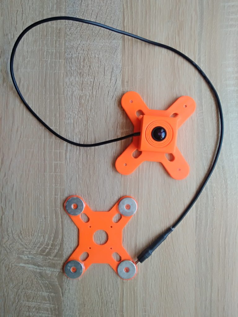
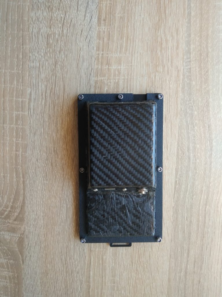
Body mounted USB camera: Here, we had quite an interesting problem. Standard USB web cameras are not tailored for body mounting, neither are they durable enough. We spent a good amount of time checking how to solve this issue, and finally, we managed to find a suitable USB camera vendor using Sony-based camera sensors. The vendor could mount any lens to the camera sensor, and the whole board came with a good amount of mounting holes. After that, one of our hardware people designed a custom mountable case for our USB camera and 3d printed it.
New extended battery: The standard battery of our Android device was around 4100mah. Unfortunately, after multiple tests, we saw that with every needed hardware capability activated, aka LTE, USB OTG, GPS, and microphone, the Android device was taking around 800-900mah per hour. And this was not enough for the whole 12 hours shift. So we took the extraordinary decision of creating our battery. Finally, we managed to produce a proof of concept 12400 mah battery replacement for our Android device. And indeed, it took 12 hours to recharge.
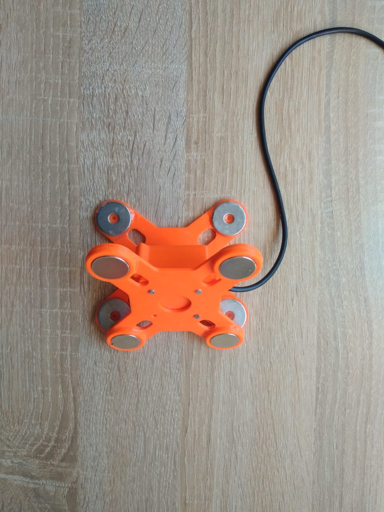
Mount for cars and bicycles: We wanted our system to support multiple different mounting points. So, to allow this to happen, we bought standard multi-camera mounts for vehicles and bikes and created adapters for our 3d printed camera to enable attachment to the stock mounts.
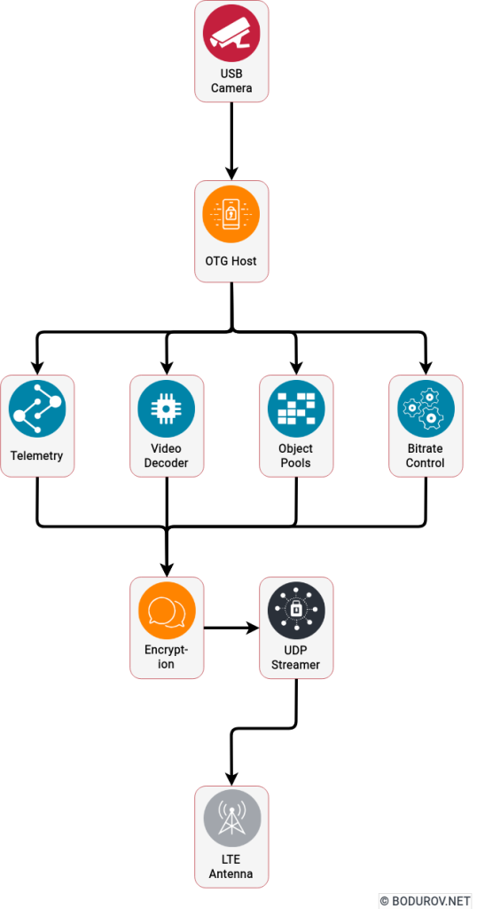
Software
On the diagram, you can see a sample architecture diagram of the solution. With that architecture, we managed to achieve 22 frames per second with streaming and encryption.
UDP streamer module: This module’s main functionality was sending UDP packets and receiving answers for these UDP packets. It sent analytics data to the Adaptive bitrate control module to decide how to switch between different formats and resolutions.
Encryption module: This module was highly optimized to perform hybrid encryption and decryption of byte objects. We managed to optimize the performance, so the module supported encryption and decryption of real-time h.264 frames coming from the USB module.
Network protocol module: Main functionality here was to construct and decode UDP datagrams messages. It used the encryption module to encrypt the data before sending it to the UDP streamer.
Adaptive bitrate and codec control module: This module controlled what type of compression strategy to use to ensure that the headquarters will receive data no matter the LTE signal.
Objects pool module: The idea of the module was to reuse different bytes arrays during the lifecycle of the h.264 packets. With around 24 frames streamed per second, creating and destroying many bytes arrays would entirely kill our application.
USB camera module: This module wrapped the communication and handling of the USB video camera bus. The idea was to support multiple different cameras and formats here.
Telemetry module: In this module, we collected all the additional data we had – current battery consumption, remaining battery time, GPS coordinates, sd card storage, etc.
h.264 decoding module: This module’s main functionality was to transfer video frame data in a different format. For example, we supported h.264 frames, png, and jpeg formats. The application was intelligent enough to decide when to switch between the different formats.
We used Java and C++ programming languages for the implementation of all the modules. The only C++ part was the USB camera module because of the low-level communication with the USB bus.
Let me share some notes on why we decided to use an Android device. We could implement our body camera system using an ARM-based board with Linux installed on top of it. It would dramatically reduce our software efforts. However, from a hardware point of view, most ARM-based boards lacked good CPUs, battery support, and housing. Not to mention, the development of a custom ARM board was entirely outside of our budget. Fortunately, our software was designed this way, so we could easily switch the hardware platform in case of investment or more considerable client interest.
In conclusion, our body camera system managed to fulfill our initial requirements for MVP. It worked well, and we made multiple videos and streams testing it in various environments and locations. Our system even managed to send data through 3G mobile cells in areas where LTE/4G was not supported.
A sample video of how the system works could be found here
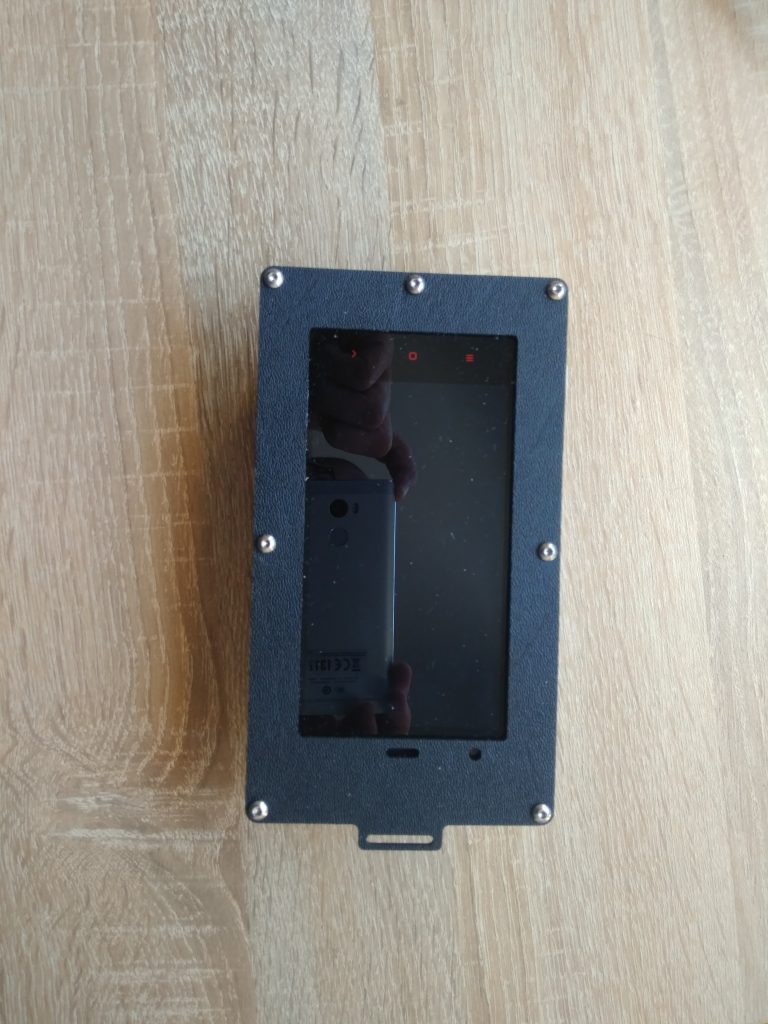
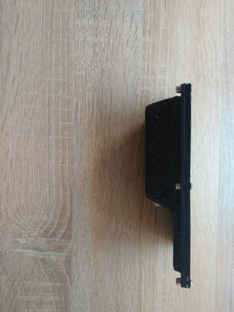
Some photos of our POC build. With that build we managed to fulfill our requirements.
So, let me go back to cybersecurity. Sorry for the long, boring mathematical-based explanation in the last part, but if one wants to use a given tool, he/she must understand how it works and, more essentially, its limits. And I shall give you my list of concerns why believing in the current cybersecurity hype can be dangerous for you and your organization:
We must not compare a Machine Learning model to the human brain: We have no idea how the human brain works, and more especially how ideas creation and generalization work. Additionally, the pure power consumption of a machine learning model is times bigger than a human brain. Sure it is faster but much more expensive. The average power consumption of a typical adult is 100 Watts, and the brain consumes 20% of this, making the brain’s power consumption around 20 W. For comparison, Google’s DeepMind project uses a whole data center to achieve the same result, which a two-year-old kid does with 20 W.
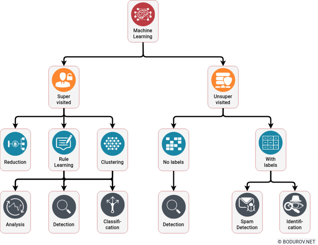
On the diagram, you can see what kind of problems Machine Learning algorithms can solve in the cybersecurity field. All of the activities listed in the last row are some form of categorization used for detection. No prevention is mentioned.
Machine learning is weak in generalization: The primary purpose of polynomial generation is to solve the so-named categorization problem. We have a set of objects with characteristics, and we want to put them in different categories. Machine learning is good at that. However, if we add a new category or dramatically change the set of objects, it fails miserably. In comparison, the human brain is excellent in generalization or, in social words – improvisation. If we transfer this to cybersecurity – ML is good in detection, but weak in prevention.
Machine Learning offers nothing new in Cybersecurity: For a long time, antivirus and anti-spam software have used rule engines to categorize whether the incoming file or email is malicious or not. Essentially, this method is just a simple categorization, where we mark the incoming data as harmful or not. All of the currently advertised AI-based cybersecurity platforms do that – instead of making the rule engine manually, they use Machine Learning to train their detection abilities.
In conclusion, cybersecurity Machine Learning models are good in detection but not in prevention. Marketing them as the panacea for all your cybersecurity problems could be harmful for organizations. A much better presentation of these methods is to call them another tool in the cybersecurity suite and use them appropriately. A good cybersecurity awareness course will undoubtedly increase your chances of prevention rather than the current level of Artificial Intelligence systems.
Lately, we see a trend in cybersecurity solutions advertising themselves as Artificial Intelligence systems, and they claim to detect and prevent your organization from cyber threats. Many people do not understand what stands behind modern Machine Learning methods and problems they can solve. And more importantly, that these methods do not provide a full range of tools to achieve the wet dream of every Machine Learning specialist – aka general Artificial Intelligence or, in other words – a perfect copy of the human brain.
But how Machine Learning works? Essentially, almost every algorithm in Machine Learning uses the following paradigms. First, we have a set of data, which we call training data. We divide this data into input and output data. The input data is the data our Machine Learning model will use to generate an output. We compare this generated output with the output of the training data and decide whether this result is good. During my learnings in Machine Learning, I was amazed how many training materials could not explain how we create these models. Many authors just started giving the readers mathematical formulas and even highly complex explanations comparing the models to the human brain. In this article, I am trying to provide a simple high-level description of how they work.
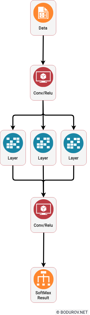
On the diagram you can see a standard Deep Learning Machine Learning model. The Conv/Relu and SoftMax parts are actually polynomials sending data from one algebraic space to another
So how do these Machine Learning algorithms do their job? A powerful mathematics branch is learning the properties of algebraic structures (in my university, it was called Abstract Algebra). The whole idea behind this branch is to define algebraic vector spaces, study their properties, and define operations over the created algebraic space. But let’s go back to Machine Learning, essentially our training data represents an algebraic space, and our input and output data is a set of vectors in that space. Luckily, some algebraic spaces can perform the standard polynomial operations, and we even can generate a polynomial rendering the input and output data. And voila, a Machine Learning model is, in many cases, a generated polynomial, which by given input data produces an output data similar to what we expect.
The modern Deep Learning approach is using a heavily modified version of this idea. In addition, it tries to train its models using mathematical analysis over the generated polynomial and, more essentially, its first derivative. And this method is not new. The only reason it has raised its usage lately is that NVidia managed to expose its GPU API to the host system via CUDA and make matrices calculation way faster than on the standard CPUs. And yeah, the definition of a matrix is a set of vectors. Surprisingly, the list of operations supported by a modern GPU is the same set used in Abstract Algebra.
In the next part, we shall discuss how these methods are used in Cybersecurity.
In this series of articles, we shall discuss one of my old projects. During that time, I had a consulting company working in IT, and this project was part of my initial steps in cybersecurity. The project started around the middle of 2015 and ceased to exist at the end of 2016. It is in body cameras, and actually, it was a competition to systems such as Axon Body 3 camera. During the lifecycle of this project, Axon cameras did not support LTE-based streaming.
The team around the project and I managed to produce a working prototype of the system, and in this series, I shall present to you how we implemented the prototype. At the end of the articles, I shall show you the actual budget for doing this prototype and analyze why it was unsuccessful.
The topic of this part will be an analysis of the advantages and disadvantages of the current video streaming network protocols. We shall start with the standard video streaming protocols, and at the end of the article, we shall discuss our modified, more secure protocol.
There are multiple different protocols for video streaming. Part of them do not support encryption, and we shall focus ourselves on those which support it.
RTMPe
Real-Time Messaging Protocol or RTMP is used to stream multimedia data – audio and video – between Flash Media Server and Flash Player. The chief utility of the RTMP stream is in the optimization of the audio and video data transfer between the server and player.
Encrypted RTMP (RTMPE) wraps the RTMP stream session in a lightweight encryption layer. Through Encrypted RTMPE, the streaming protocol provides low-level stream encryptions for high-traffic sites. RTMPE uses the Anonymous Diffie-Hellman key exchange method. In this algorithm, two parties – the media server and the flash player – establish a shared secret key over an insecure channel.
The standard RMTP protocol uses TCP, and RTPMe uses an encryption model based on a shared secret.
HTTP Live Streaming Encryption Methods
While the HLS supports AES-128 encryption, there are two different ways to implement the standard in practice.
Broadcasters can use one key to encrypt the entire video stream, but that also means the whole stream is unprotected if an unauthorized third party intercepts the secret key.
Alternatively, each segment of a stream can be encrypted with a different key. That way, users can access only a few seconds of video with each specific key. Broadcasters might choose this method if the video content their sharing is highly sensitive.
As it comes from its name, HTTP Streaming uses HTTP to resemble MPEG-DASH. It works by breaking the overall stream into a sequence of small HTTP-based file downloads, each downloading one short chunk of a broad, potentially unbounded transport stream. A list of available streams, encoded at different bit rates, is sent to the client using an extended M3U playlist. HTTP is a TCP-based protocol, as well.
MPEG DASH Encryption
Dynamic Adaptive Streaming over HTTP (DASH), also known as MPEG-DASH, is an adaptive bitrate streaming technique that enables high-quality streaming of media content over the Internet delivered from conventional HTTP web servers. Similar to Apple’s HTTP Live Streaming (HLS) solution, MPEG-DASH works by breaking the content into a sequence of small segments, which are served over HTTP. Each piece contains a short interval of playback time of content that is potentially many hours in duration, such as a movie or the live broadcast of a sports event.
MPEG DASH supports a Common Encryption mode (CENC), which Bento4 implements. Encrypted MPEG DASH presentations should also include the proper signaling in the MPD to inform the player of what DRM(s) can be used to obtain the decryption keys for the streams. An MPD can contain DRM signaling for several DRMs (either just one or multiple entries if the same stream can reach players with different DRM technologies).
Again MPEG Dash is based on HTTP, aka TCP. In that case, DRM encryption is usually based on a public, private key encryption scheme.
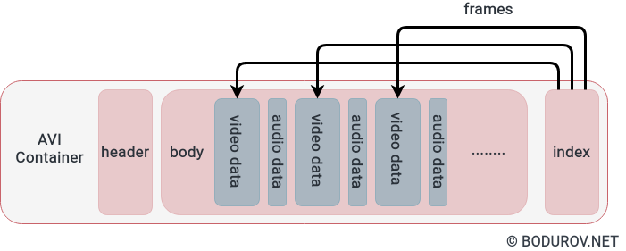
On the diagram, you can see a standard AVI container. The video data objects are x264/h264 frames, which most of the streaming protocols encrypt, encode, and stream.
Our Modified Streaming Protocol
As you can see from the upper paragraphs, every standard encryption protocol was designed to stream data from a centralized server to a list of devices. Most of them use the traditional HTTP delivery networks to speed up their streaming. In our case, we had an entirely different problem. We had to stream encrypted content from multiple body cameras to a centralized server and, after that, restream the video from the server to a web browser-based dashboard. LTE networks can be quite fast when you have proper coverage, but when your signal drops, your network speed drops significantly, as well. So we decided to design our video streaming protocol, and I shall list our requirements:
Based on UDP: Sending TCP data through LTE can hurt your performance a lot. That’s the reason we decided to establish our protocol on UDP and to implement packet control.
Based on X264: X264 is an open-source implementation of the H.264 protocol. It is already implemented in most Android devices and is supported natively. The encoding rate is reasonable.
Codec agnostic: In the future, we wanted to support H.265 and its open-source implementation. Thus the protocol had to be code agnostic.
To use hybrid encryption: Most of the listed protocols do not use a hybrid encryption approach. We wanted our protocol to have better authentication and encryption mechanism, and that’s why we decided to use hybrid-based encryption on top of RSA and AES-GCM. We changed the keyphrase and IV for AES on every packet frame sent to implement the encryption correctly.
Binary-based: Keeping in mind that LTE is usually sold using monthly plans. These plans are generally only a couple of gigabytes. So we ended up making a binary-based protocol. Any other protocols, and especially the semantic-based ones, would result in more significant data consumption.
Adaptive Bitrate: The LTE network bandwidth depends on how strong a radio signal your device has. The weaker the signal, the lower the bandwidth. We had to implement an adaptive bitrate strategy, which lowered the resolution in a weaker signal. This way, you could receive frames no matter how strong is your LTE cell signal.
Our proof of concept implementation managed to fulfill these requirements. The finished network protocol was fast enough and binary compatible. It supported adaptive bitrate and was code agnostic.
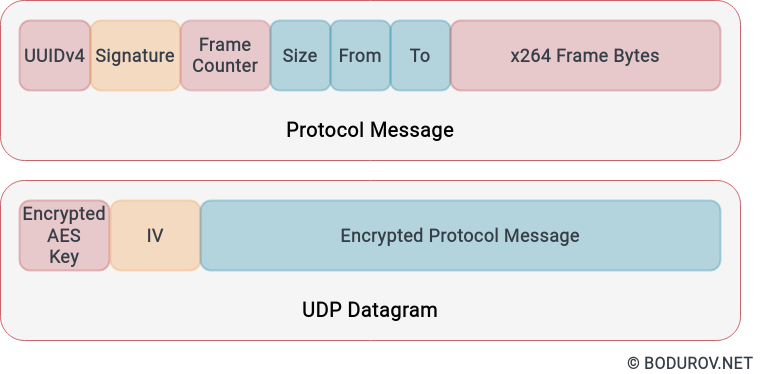
On the diagram, you can see a sample datagram of this protocol. The MTU was 1500 bytes to support all kinds of equipment, but not only with jumbo frames.
We used an UUIDv4 and RSA signature for authentication purposes. After that, you have multiple fields as a counter in the index, date, packet size, and an array of bytes. The implementation stripped down an h.264 frame to multiple UDP packets and sent them together. The server combined them back to the h.264 packet and appended them to corresponding files.
We saw that it is better to have adaptive logic on the codec level during our tests for the protocol. For example, a simple JPEG stream was much better when the signal was weaker.
In the next part, we shall discuss how we created our body camera device and its software. We shall discuss our streaming server implementation in the final third part, give you a budget, and explain why the whole business model did not work as expected.
Data storage was never such a big issue in the past. However, nowadays, every day, we produce a massive amount of data. The newest form of storing data is DNA sequencing. The current leader in long-term storage is magnetic tape. Unfortunately, magnetic tapes can store data only for thirty years. One device has the capacity of only a terabyte of data. In comparison, DNA Fountain-based storage could store data at a density of 215 petabytes per gram of DNA.
But to store a massive amount of data in such a tiny medium has its unique list of dangers. Let us look at those potential risks one by one.
Risk for Computers: At the moment, there is no threat to your computer by storing data into a DNA sequence. However, similar to every data medium, hackers can use DNA storage to keep and spread malware.
Intentional insertion of malware: Unfortunately, one of the main disadvantages of using DNA-based storage is that the physical world can modify your DNA. A skillful attacker can create an entirely different set of threats such as biological viruses or bacterias, transmitting and injecting malware programs into your DNA storage.
No way to erase the storage: Once written, DNA is usually quite tricky to modify. We should treat the DNA-based storages such as highly capable compact discs with slow rewriting capabilities. The most trustful way to erase such storage is to eradicate it.
Easier to physically steal: How do you assure the physical security of under one gram of data? Do we store it in a safe? Sure, but hackers can make a hole in your safe and steal your data. The size of DNA-based storage devices introduces an entirely different set of challenges for your physical security.
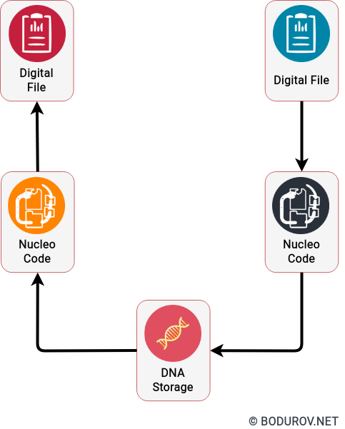
A sample diagram of how DNA-based storage works. To record your data into DNA, you can create an entirely new footprint with your data encoded as Nucleo code. After that, you have to synthesis it into a DNA sequence.
Benefits of using DNA based storages:
Despite the threats, we could still prefer DNA-based storage in the future because it can store data for thousands of years, unlike hard drives. The information stored in DNA will not go extinct until human beings exist. These characteristics make DNA-based storage a perfect replacement for the currently used cold backup systems such as magnetic tapes.
How to control the security threats associated with DNA-based storages?
Fortunately, at this current moment, there is no significant adoption of DNA-based storage devices. The current leader is magnetic tape and will stay the same for foresee future. At the same time, the ordinary person does no use magnetic tape to store data. Usually, we use a collection of hard drives with multiple copies of our data. With this in mind, we can deduce that DNA-based storage will find its use mainly in data centers and big corporations’ data storage departments. Still, it is essential to understand that we must implement an entirely different set of techniques when we speak about DNA. With our current speed of technological development, it is quite possible to have DNA-based storage in our homes or bodies in the next decade or two.
Way Out of these Threats:
In conclusion, DNA-based storage is just another data medium. To secure the data stored there, we can use the same set of principles for storing data in hard drives. We could use strong encryption, excellent authentication, and a sound policy to store your data on a digital device or in paper documents.